As a result of the almost inevitable mismatch of an RF transmission line or feeder, neither the voltage nor the current is constant along the length of the line, that is, the voltage and current will vary according to the point along the line at which they are measured.
The performance of an RF transmission line can therefore be judged only by the measurement of its standing wave ratio (SWR) as defined in Chapter 7.SWR is measured by means of a circuit known as a 'reflectometer'. The principle of operation is that when an RF transmission line is terminated in an impedance other than the characteristic impedance, ie when the line is not properly matched, part of the signal is reflected back long the line. The ratio of the power reflected to the power incident on the termination is directly related to SWR.

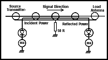
Fig 10.7. Basic reflectometer circuit
The basic reflectometer circuit is shown in Fig 10.7. An insulated wire is threaded down between the outer shield and the insulation of a coaxial cable. When an RF signal passes down the coaxial cable part of it is coupled into the wire. This RF signal is rectified and the resulting DC is displayed on a milliammeter. This is an indication of the 'forward' power. A reflected signal that is travelling from termination to source will also be coupled into the wire. However, it will do so in such a way that it is rectified by the other diode and displayed by the other milliammeter. This is the 'reflected' power. SWR meters can be made easily from published data. These generally use a somewhat different circuit which avoids the centre tap on the wire threaded down the coaxial cable. A single meter is usually switched to read forward or reflected power.

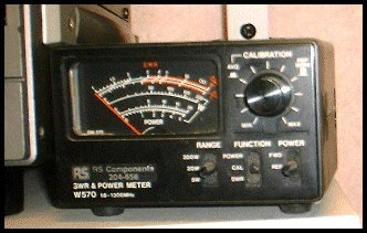
An SWR meter. This wideband SWR meter contains two sensors to cover the range 1.8-1300MHz. It also measures average RF power and peak envelope power (PEP)