The reasons for measuring frequency in the amateur station are:
Assuming that a receiver having a reasonably accurate frequency calibration is available, the calibration can be checked against short-wave broadcast stations of known frequency or against standard frequency transmissions, for example MSF Rugby (2.5,5 and 10MHz) or WWV (10, 15,20 and 25MHz).
An accurate calibration may also be made by listening to the 'pips' produced in the receiver by harmonics of a crystal oscillator. When used in conjunction with a general-coverage receiver, a 100kHz crystal is usually adequate for checking frequencies up to about 4MHz. For higher frequencies, the spacing between 100kHz marker points may be too small to resolve, and a crystal of 500kHz or preferably 1MHz should be used in addition. If the receiver covers only the amateur bands, the band-spread is normally adequate to resolve the harmonics from the 100kHz crystal.
100kHz crystals for use in frequency standards are available with frequency accuracies of 0.002%. One of these should be considered as the prime frequency standard.
A calibration graph or table can now be drawn up for each range of the receiver. It must be kept in mind that the accuracy of this depends on the precision of the receiver dial mechanism, its logging arrangement and the presence of band-spread. The frequency of operation of a transmitter may then be measured using the receiver, calibrated as above.
Obviously the receiver cannot be tuned to even a low-power transmitter in the immediate vicinity, but it can 'listen to' the output of the VFO, the frequency of which may then be determined and hence the final output frequency of the transmitter. Although the VFO is screened, it will be found necessary to considerably reduce the receiver RF gain. The tuning range of a VFO can be quite easily adjusted to the required value in this manner.
The absorption frequency meter consists of a coil tuned by a variable capacitor, with a scale calibrated in frequency. It operates by absorbing power from a tuned circuit when tuned to the same frequency as that circuit. The tuned circuit must therefore be activated, and the absorption of power is indicated by a small change or flick in the transistor current flowing through the tuned circuit as the resonance point is passed.

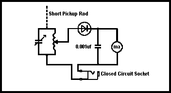
Fig 10.3. Absorption wavemeter with micro-ammeter as indicator of resonance
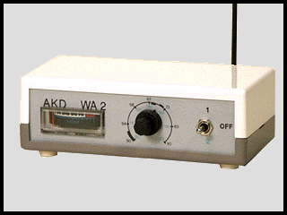
An absorption wavemeter for the VHF/UHF bands
Such a frequency meter has the advantages of:
The disadvantages are as follows:
An absorption frequency meter is useful for checking that frequency-multiplying stages are tuned to the correct harmonics, for example, in checking whether a particular stage being driven by a 7MHz oscillator is tuned to 21MHz (third harmonic) or to 28MHz (fourth harmonic). Checking of harmonics is necessary in the initial tuning up of VHF equipment, which may operate on the 18th harmonic or higher of a given crystal frequency.
A rectifier and a microammeter can be added to the absorption frequency meter so that the meter itself can indicate resonance. This is shown in Fig 10.3. With the addition of a short antenna coupled to the coil, this arrangement becomes the so-called 'field strength meter' which may also be used for searching for parasitic oscillations in the transmitter. If a close-circuit jack for headphones is connected in series with the meter, the circuit can be used for monitoring an amplitude-modulated transmission.
This is more flexible than the absorption meter in that the tuned circuit under test does not have to be energised. It consists of an oscillator using a FET. When the oscillator is tuned to the frequency of the tuned circuit under test, power is absorbed from the oscillator. This is indicated by a dip in the source current of the FET. The dip oscillator has the same accuracy as the absorption meter but has the disadvantage that a power source is needed.
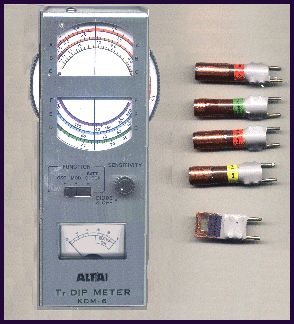
A FET dip meter. Frequency range is selected using plug-in coils (right). The coloured band on each coil corresponds to a same coloured range on the tuning dial
This type of frequency meter utilises integrated circuits to count electronically the number of complete sine waves in a given period. Although these digital integrated circuits are themselves complex, the principle of operation of the digital frequency meter (DFM) is quite simple; it consists of four major circuits, the 'clock', the 'gate', the 'counter' and the 'display'.
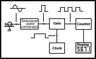
Fig10.4. Block diagram of a simple digital frequency meter
The clock produces a series of pulses of length 1s, 100ms, 10ms, 1ms and so on. These pulses are derived from a crystal-controlled 1MHz (or 5MHz) oscillator and their duration is controlled to a very high degree of accuracy. The pulses are applied to the gate which may be considered as an electronic on/off switch operated by the clock.
When the clock pulse opens the gate, the sinusoidal signal whose frequency is to be measured, having been converted to a train of square pulses, is allowed to pass to the counting circuits. As the name suggests, these count the number of pulses (cycles) which arrive while the gate is open and then pass the answer to the display circuits which present the answer in the form of a digital display.
The accuracy of the DFM depends upon the accuracy of the clock. If this produces pulses which are longer than they should be, the gate remains open for a longer period and more pulses are counted. If the clock pulse is too short, fewer pulses are counted. Accuracy can be increased if the clock oscillator crystal is housed in a crystal oven (thermostatically controlled) to hold the crystal temperature more or less constant.
The counting circuits will only respond to complete pulses and this may give rise to errors in measurement. For example, consider a signal of frequency of, say, 5671Hz. If the gate is open for only 0.1s, 567 whole pulses will be counted and it appears that the frequency is 5670Hz. If the gate is opened by the clock pulse for 0.01s, only 56 complete pulses are counted, suggesting that the frequency is 5600Hz and so on. Thus the duration of the clock pulse plays an important point in determining the accuracy of measurement.
In practice, the clock pulse duration or 'resolution' of a DFM can be set by a switch on the front panel of the instrument. With careful use an accuracy of ±5Hz can be achieved. This is more than adequate for most amateur applications.
Many types of IC may be used in digital frequency meters. The more common (and cheaper) types will permit measurement of frequencies up to 100MHz or so, and this may be extended by the latest IC's and pre-scalers to well over 1000MHz.
The digital frequency meter is the most accurate type of frequency meter available, under ideal conditions. They can be confused by multiple signals being fed into the input and usually latch onto and count only the strongest signal.
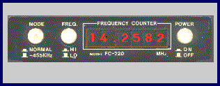
A 5-digit frequency counter. It has a maximum resolution of 10kHz at this setting.
The frequency counter in the above photograph contains specialised IF offset circuitry. This can be switched in as required and is capable of being used to measure the local oscillator frequency in a single conversion receiver (455kHz). It can automatically offset from this value, to display the actual frequency to which the receiver is tuned to receive. When measuring the frequency of a operating transmitter, it is usually sufficient to attach a short piece of wire to act as an antenna to collect a sample of the radiated RF.