The parallel and series connections of an inductor and a Capacitor to form a tuned circuit are shown in Figs 2.11(a) and 2.11(b) respectively. At one particular frequency, the numerical values of the reactance of the inductor and the reactance of the capacitor will be equal (see Fig 2.6), that is: XL = XC
or![]()
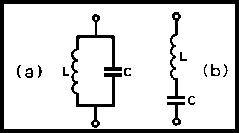
Fig 2.11. Arrangement of capacitor and inductor to form tuned circuit: (a) parallel-tuned circuit; (b) series-tuned circuit
This can be simplified to give:
![]()
(fo is in hertz when L is henrys and C in farads). fo is called the 'resonant frequency' of the tuned circuit.
There are inevitably losses associated with all tuned circuits because neither the inductor nor the capacitor is perfect; these losses are always assumed to be resistive and are shown, when required, as a resistor R in series with the inductor.
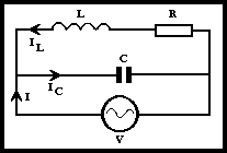
Fig 2.12. Current and voltage relationships in a parallel-tuned circuit
Consider the circuit of Fig 2.12. It can be shown that the impedance at resonance of this circuit is L / CR ohms. Hence by Ohm's Law:
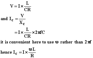
Similarly it can be shown that the current which flows through the inductor is:
![]()
Thus the currents flowing through the capacitor and the inductor IC
and IL are both greater than the input current I by a factor of
![]() .
This factor is called the 'magnification factor' of the tuned circuit. It is
generally just known as the 'Q' and may be quite large, thus:
.
This factor is called the 'magnification factor' of the tuned circuit. It is
generally just known as the 'Q' and may be quite large, thus:
![]()
The current which flows through L and C is known as the 'circulating current'. This, as shown above, can be quite large although the current I taken from the supply V may be small.
As a capacitor generally has quite low losses when correctly used, the Q of a tuned circuit is determined by the inductor. The range of Q obtainable is roughly 100 to 400 depending on the type and form of the inductor. The Q may be reduced by the load placed upon the tuned circuit by the circuit which follows it.
The currents flowing through the inductor and capacitor vary with the frequency as they depend upon the term:
![]()
If the ratio of IL and I is plotted against frequencies above and below the resonant frequency, a curve similar in shape to Fig 2.15 is obtained. This curve is called a 'response curve' because it indicates how the tuned circuit responds to different frequencies; it is also known as a 'resonance curve'. The shape of this curve is determined by the Q - the greater the Q, the higher and narrower the curve becomes.
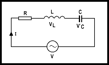
Fig 2.13. Current and voltage relationships in a series-tuned circuit
The above discussion also applies to the series-tuned circuit (see Fig 2.13) in which the impedance is at a minimum at resonance and is equal to R. The voltages across the inductor and capacitor, not the current flowing in each, are calculated as before and the increase in the voltages is equal to Q. If in this case, the ratio VL/ VC is plotted, a similar resonance curve is obtained.
The value of the impedance of the parallel-tuned circuit at resonance is known as the 'dynamic resistance'. This is a fictitious resistance and exists for alternating currents of the resonant frequency. Its symbol is RD .
The dynamic resistance can be expressed in terms of Q as follows:
![]()
A good-quality tuned circuit will have RD of about 50,000Ω. The DC resistance is usually very low.
The parallel-tuned circuit is by far the most commonly used one.
The series-tuned circuit, having minimum impedance at resonance, accepts maximum current at resonance and is sometimes known as an 'acceptor circuit' (see Fig 2.14(a)).
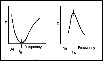
Fig 2.14. Impedance/frequency characteristics of (a) series-tuned circuit; (b) parallel-tuned circuit
In a parallel-tuned circuit, the impedance is at maximum at resonance. The parallel-tuned circuit is often called a 'rejecter circuit' because, having a high impedance at resonance, it rejects current at this frequency (see Fig 2.14(b)).


