The principle of electromagnetic induction is illustrated in Fig 2.9(b). This is the basis of the transformer in which an alternating current flowing in the winding P creates an alternating magnetic field which cuts the turns of the winding S. It is therefore obvious that transformers can only operate on an alternating supply!
Fig 2.9. Electromagnetic induction. (a) Relative movement of magnet and coil causes a voltage to be induced in coil; (b) when current In one of a pair of coupled coils changes in value, a voltage is induced in the second coil.
Transformers perform many vital functions in electrical and radio engineering; for example. the transfer of electrical energy from one circuit to another and, implied in the latter, the transformation of an alternating voltage upwards or downwards.
If in a transformer the number of turns on the primary winding is np, the number of turns on the secondary winding is ns, the voltage across the primary is Vp, and the voltage across the secondary is Vs , then:
![]()
The term ns /np called the 'turns ratio', which may be less than or greater than unity: thus the transformer may 'step down' or 'step up'. The relationship between the currents in the primary and secondary windings is similarly:
![]()
If primary impedance is Zp and secondary impedance is Zs , then:
![]()
This is particularly important; note that the impedance ratio is equal to the turns ratio squared whereas the voltage ratio equals the turns ratio itself.
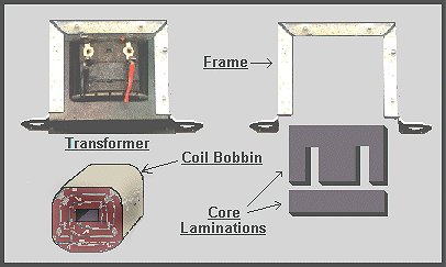
Photo of a typical small transformer, both assembled and in its component parts.
The 'E' and 'I' iron core core laminations are offset made from thin sheet iron, built up in layers. The E's and I's being offset for each layer. The winding of power transformers are normally wound on a plastic bobbin, through which a laminated silicon iron core is assembled, as in the case of the iron-cored inductor.


