Basic radio theory, circuits and calculations
Calculations
A number of sample calculations involving resistance, capacitance,
inductance, reactance and resonance follow.
The mathematics involved are explained in Appendix 2. The calculations
required in the RAE are generally more simple than these and often the answers
can be obtained by inspection or approximation.
Example 1
A current of 50mA flows through a resistor of 1.5kΩ. What is the voltage across
the resistor?
By Ohm's Law

Example 2
In a stage of a receiver, 12V are applied across a potential divider of 3300Ω
and 2700Ω. What is the current through the resistors?
By Ohm's Law


Example 3
Resistors of 33kΩ and 27kΩ are connected in series. What is the effective
resistance?

Example 4
Resistors of 100Ω and 150Ω are connected in parallel. Find the effective
resistance.
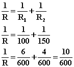
Therefore, by cross-multiplying

Alternatively, the value of two resistors in parallel can be found by
dividing the product of their values by the sum.

Example 5
In the smoothing circuit of a power supply, capacitors of 8μF, 4μF and 2μF are
connected in parallel. What is the effective capacitance?
Effective capacitance

Example 6
Capacitors of 220pF, 470pF and 0.001μF are connected in parallel. What is the
effective capacitance?
Before addition can be effected, the values must first of all be expressed
either in picofarads or in microfarads. Since there are 1,000,000pF to 1μF,

Therefore the effective capacitance is

Alternatively,

and

so that the effective capacitance is

Example 7
Two capacitors of 0.001μF and 0.0015μF respectively are connected in series.
Find the effective capacitance.


Example 8
Two inductors of 10 and 20μH are connected in series; two others of 30 and 40μH
are also connected in series. What is the equivalent inductance if these series
combinations are connected in parallel? Assume that there is no mutual
induction.
The 10 and 20μH coils in series are equivalent to (10 + 20) = 30μH
The 30 and 40μH coils in series are equivalent to (30 + 40) = 70μH
These two equivalent inductances of 30μH and 70μH respectively are in
parallel and therefore equivalent to one single inductance of

Example 9
What power is consumed by a transmitter taking 1.5A at 12V?

Example 10
What is the input power of a transmitter stage running at 24V, 2.5A?

Example 11
Find the power dissipated by a 15Ω resistor when it is passing 1.2A.

Example 12
The current at the centre of a given λ/2 antenna is found to be 0.5A. If this
antenna has a radiation resistance of 70Ω, find the radiated power.

Example 13
A transmitter output stage is running at 20V, 3A. It is found to produce a
current of 0.9A RMS in a load resistance of 50Ω. Find (a) the input power, (b)
the output power, and (c) the efficiency of the stage.
(a) input power = W = DC volts x DC amperes
= 20 x 3 = 60W
(b) output power = W = (load current)2 x load resistance
= 0.9x0.9x50 = 40.5W output power
(c) efficiency


or

Example 14
What is the reactance of a 15H smoothing choke at a frequency of (a) 50Hz and
(b) 400Hz?
(a)

(b) At eight times the frequency, X is eight times as great, ie 37,600Ω.
Example 15
A medium-wave coil has an inductance of 150μH. Find the reactance at a frequency
of 500kHz.

Note how the frequency in kilohertz must be multiplied by 1000 to bring it to
hertz, and how the inductance in micro-henrys must be divided by 1,000,000 to
bring it to henrys.
Example 16
What is the reactance of a 2μF smoothing capacitor at a frequency of (a) 50Hz,
and (b) 400Hz?
(a)
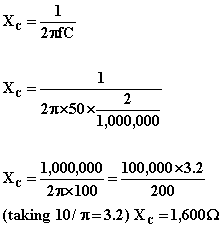 where
f is the frequency and C the capacitance in farads.
(b) At eight times the frequency, X is one-eighth of the above value, ie
200Ω.
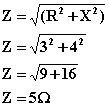
Example 17
A coil has a resistance of 3Ω and a reactance of 4Ω. Find the impedance.
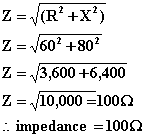
Example 18
Given a series circuit with a resistance of 60Ω and a capacitor with a reactance
(at the working frequency) of 80Ω, find the impedance of the circuit.
Example 19
Suppose the coil of Example 17 were connected (a) across 15V DC and, (b) across
15V AC (of frequency at which the reactance was 4Ω). Find the current in each
case.
(a) At DC the reactance is zero and only the resistance opposes the passage
of current. By Ohm's Law

(b) At AC Ohm's Law may still be used, provided Z (the impedance) is used in
place of R (the resistance).

Example 20
In the series circuit of Example 18, suppose the circuit were connected (a)
across 240V DC and (b) across 240V AC (of frequency at which the reactance was
70Ω). Find the current in each case.
(a) A capacitor blocks the passage of direct current, therefore the current
is zero amperes.
(b) Ohm's Law still holds, provided Z (the impedance) is used in place of R
(the resistance).

Example 21
Find the capacitance required to resonate a 10H choke to 500Hz.
For resonance

hence
 farads
 microfarads
and inserting the given values

Example 22
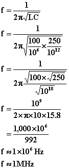
A coil of 100μH inductance is tuned by a capacitance of 250pF. Find the resonant
frequency.
For resonance

hence
Example 23
What value of inductance is required in series with a capacitor of 500pF for the
circuit to resonate at a frequency of 400kHz?
From the resonance formula

the inductance is

Expressing the frequency and the capacitance in the basic units (f = 400x103Hz
and C = 500x10-12F)
=

Taking π2 = 10
=


Example 24
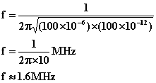
If the effective series inductance and capacitance of a vertical antenna are
20μH and 100pF respectively and the antenna is connected to a coil of 80μH
inductance, what is the approximate resonant frequency?
The antenna and coil together resonate at a frequency determined by the
capacitance and the sum of the antenna effective inductance and the loading coil
inductance.

Here the relevant values of inductance and capacitance expressed in the basic
units are

Therefore
Example 25
An alternating voltage of 10V at a frequency of 5/π MHz is applied to a circuit
of the following elements in series: (i) a capacitor of 100pF, (ii) a
non-inductive resistor of 10Ω.
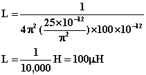
(a) What value of inductance in series is required to tune the circuit to
resonance?
(b) At resonance, what is the current in the circuit?
(a) For the calculation of the inductance, the resistance can be ignored,
since it has no effect on the resonant frequency, which is given by

rearranging

Expressing the frequency and the capacitance in the proper units (f=5x10⁶/π
Hz and C=100x10-12F)
(b) At resonance, the inductive and capacitive reactances cancel out and the
circuit has a purely resistive impedance of 10Ω. The current I through the
circuit at resonance can then be calculated directly from Ohm's Law: I = V/R.
Since V = 10V and R = 10Ω, the current at resonance is

Example 26
A tuned circuit having a Q of 120 resonates at a frequency of 80kHz. What is its
bandwidth at the -3dB level?
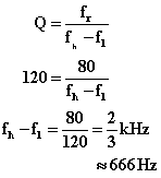
Bandwidth is approximately 666Hz.
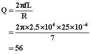
Example 27
A coil of inductance 25μH has a resistance of 7Ω at a frequency of 2.5MHz. What
is its Q at this frequency?


![]()


![]()
![]()
![]()
![]()
![]()
![]()
![]()
![]()
![]()
![]()
![]()
![]()
![]()
![]()

![]()
![]()
![]()
![]()

 where
f is the frequency and C the capacitance in farads.

![]()
![]()

![]()
![]() farads
farads![]() microfarads
microfarads
![]()

![]()
![]()
![]()
![]()

![]()


![]()
![]()

![]()

