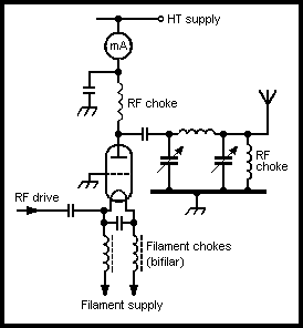
The main use of valves as RF power amplifiers is now as a separate amplifier unit driven by the standard transceiver. The amplifier is generally a 'linear amplifier' operating in the grounded-grid mode as it is required to amplify an SSB waveform. These amplifiers are readily available commercially at ratings well above the UK licence limit. They are quite often home-made as the circuit is quite simple, using relatively few, but some large, components.
Two categories of valve are in use. The first category is the medium-power transmitting valve. Such types with their approximate outputs are: two 572B valves (800-1000W), three 811A valves (600W), two 813 valves (1000W), one 3-5000Z valve (1000W). At VHF and UHF the 4CX250B is used. These valves require a power supply of about 2000V (see Chapter 6).
The other category is colour-TV line output valves ('sweep tubes') with up to four connected in parallel. These are indirectly heated tetrodes used as triodes by connecting both grids together. They have a maximum anode voltage of about 700V (peak E1 is 7kV), with maximum anode current of the order of 350mA. These are not continuous ratings, so the anode dissipation is 25-30W. Such valves are satisfactory at the peaky nature of the SSB waveform. They have been used in commercial equipment and are used in home-built amplifiers. Typical types are 6JS6, 6KD6, 6LQ6 and 6HF6 (American) and PL509 (European, 40V 0.3A heater); they provide an output of about 400W at an anode voltage around 700V.
In the grounded-grid mode it is necessary to isolate the filament of a directly heated valve from ground at RF. This is achieved by supplying the filament via a bifilar choke wound on a ferrite rod as shown in Fig 4.17. There is generally sufficient isolation between cathode and ground at RF if the cathode is indirectly heated. The remainder of the circuit is as that of the standard Class C RF stage. The anode tuned circuit is the standard 'pi' arrangement to attenuate unwanted frequencies.

Fig 4.17. Grounded-grid RF power amplifier
The input drive power required by the grounded-grid circuit is somewhat greater than in the grid-driven amplifier. This is offset by the fact that a portion of the drive power appears in the output. The drive power required is within the output capability of most transceivers.
It must always be remembered that an overdriven linear amplifier can create serious interference due to the resulting non-linearity, distortion and excess bandwidth. In other words a linear amplifier should not be used at more than about 75% of its rating.
Few high-power solid-state amplifiers are commercially available; designs for home-built units have been published. No doubt others are available in the application reports of the transistor manufacturers. Problems such as protection against high SWR and power supply failure are likely to be worse at higher powers.