The output of a transmitter is known as the 'carrier wave'. This is an alternating waveform of the desired amplitude and frequency. Ideally it is a pure sine wave, ie it should not contain harmonics, nor any other unwanted frequencies which might cause breakthrough to other services (TV, broadcast etc). The amplitude of the carrier wave depends upon the power and the output impedance of the transmitter which is most likely to be 50 to 75Ω .
In order that a transmitter may be used to convey a message or other information to a listener, the carrier could be switched on and off (ie keyed) in order to produce the dots and dashes of the Morse code (CW telegraphy). Alternatively, some characteristic of the carrier wave may be varied in sympathy with the message. This process is called 'modulation'. Modulation may be achieved by the periodic variation of:
(a) amplitude, hence 'amplitude modulation' (AM); or
(b) frequency, hence 'frequency modulation' (FM).
The rate of variation of amplitude or frequency of the carrier wave. ie the 'modulating frequency' (fm) is assumed to be low compared with the carrier frequency (fc ).
For optimum performance, each mode of modulation requires a particular form of demodulation circuit in the receiver. These are described in Chapter 5.
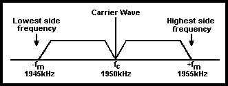
Fig 4.11. Relationship between carrier and sidebands in an AM system
In all modulation processes frequencies above and below the carrier wave are produced, these being termed 'side frequencies'. The bands of side frequencies are called 'sidebands'.
In AM, the highest side frequency is the sum of the carrier frequency (fc) and the highest modulating frequency (fm) eg if fc is 1950kHz and fm is 5kHz, the highest and lowest side frequencies are 1955kHz and 1945kHz, ie the sidebands extend from 1955kHz to 1945kHz as shown in Fig 4.11. The 'bandwidth' occupied by this transmission is 10kHz.
For FM this situation is much more complex and theoretically the sidebands in an FM system are infinitely wide. The change, which is both positive and negative, in the frequency of the carrier (known as the 'centre frequency') is called the 'deviation'. The deviation is proportional to the amplitude of the modulating signal, so that the limits of the 'swing', ie twice the deviation, are determined by the peaks of the modulating voltage. The rate at which the carrier frequency is deviated is equal to the frequency of the modulating signal, eg if a carrier wave of 7075kHz is modulated by a 3kHz tone of specified amplitude to produce a deviation of 2.5kHz, the carrier frequency will swing between 7072.5 and 7077.5kHz (ie the swing is 5kHz) 3000 times per second. If the amplitude of the 3kHz tone were doubled, the carrier frequency would swing between 7070 and 7080kHz but the rate of variation would still be 3kHz.
The ratio of the deviation to the frequency of the modulating signal is the 'modulating index'. This ratio is obviously not constant, as the deviation depends on the amplitude of the modulating signal. Its limiting value, or the ratio of the maximum deviation to the highest modulating frequency, is called the 'deviation ratio'. In the example quoted earlier, the deviation ratio is 2.5kHz divided by 3kHz or 0.833 for the first given amplitude, and 5.0kHz divided by 3kHz or 1.67 when the amplitude of the modulating signal is doubled.
For the faithful reproduction of speech and music, it is necessary to transmit frequencies over the whole audible range (ie approximately 20Hz to 16kHz). In a communication system, intelligibility rather than fidelity is of prime importance and in the overcrowded conditions of the present-day amateur bands it is obviously most important to ensure that no transmission occupies a greater bandwidth than is absolutely necessary for intelligible communication.
Experience shows that the intelligible transmission of speech requires that only frequencies of up to 2.5-3kHz need be transmitted. Thus the bandwidth of an AM transmission should not be greater than about 5-6kHz. This restriction of the audio bandwidth is achieved by the use of a low-pass filter having a cut-off frequency of about 2.5kHz in the low-level stages of the modulating circuits.
In FM, as applied to communication, the deviation should be restricted so that the bandwidth occupied is approximately the same as in an AM transmission. This is known as 'narrow-band frequency modulation' (NBFM) and the deviation used is ±2.5kHz or so (as compared with the ±75kHz of the high-fidelity broadcast station).
The amplitude-modulated wave is shown graphically in Fig 4.12. Here (a) represents the unmodulated carrier wave of constant amplitude and frequency which, when modulated by the audio-frequency wave (b), acquires a varying amplitude, as shown at (c). This is the modulated carrier wave, and the two curved lines touching the crests of the modulated carrier wave constitute the modulation envelope. The modulation amplitude is represented by either x or y (which in most cases can be assumed to be equal), and the ratio of this to the amplitude of the unmodulated carrier wave is known as the 'modulation factor' or 'modulation depth'.
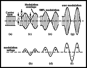
Fig 4.12. Graphical representation of amplitude-modulation wave
This ratio may also be expressed as a percentage. When the amplitude of the modulating signal is increased, as at (d), the condition (e) is reached, where the negative peak of the modulating signal has reduced the amplitude of the modulated wave to zero, while the positive peak increased the carrier amplitude to twice the unmodulated value. This represents 100% modulation, or a modulation factor of 1.
Further increase of the modulating signal amplitude, as indicated by (f), produces the condition (g), where the carrier wave is reduced to zero for an appreciable period by the negative peaks of the modulating signal. This condition is known as 'over-modulation'. The breaking up of the carrier in this way causes distortion and the introduction of harmonics of the modulating frequencies, which are radiated as spurious sidebands; this causes the transmission to occupy a much greater bandwidth than necessary, and considerable breakthrough is likely to be experienced in nearby receivers (see Chapter 9). The radiation of such spurious sidebands (sometimes known as 'splatter') must be avoided at all costs. There is no direct equivalent of over-modulation in an FM system; an increase in the amplitude of the modulating signal will cause an increase in the deviation produced by the transmitter. The recommended deviation would therefore be exceeded and the transmission would occupy a wider bandwidth, ie it would be FM rather than NBFM.
Ultimately the maximum deviation possible is restricted by the design of the RF circuits in the transmitter and the receiver, and attempts to exceed this will result in a distorted signal. However, this would require gross maladjustment and really excessive audio input to the frequency modulator.
Consideration of Fig 4.11 (above) indicates two significant aspects of an amplitude modulation system.
(a) The carrier wave itself does not contain any intelligence, its frequency
being fc .
(b) Both sidebands are identical as they both result from the modulating
frequency fm and the width of each is equal to the highest modulating frequency.
Both sidebands therefore carry the same intelligence.
It follows that the carrier need not be transmitted and, as both sidebands contain the same intelligence, only one of them need be transmitted. This has led to the adoption of the system known as 'single sideband suppressed carrier', generally abbreviated to 'SSB'.
Keying is the switching on and off (by a Morse key) of a transmitter in order to break up the carrier wave into the dots and dashes of the Morse code. Keying implies the switching of an electric circuit and therefore, in order to minimise sparking at the contacts of the key, it should take place at a point in the circuit where the power or current is at a minimum.
In order to avoid the possibility of causing chirp and small changes in transmitter frequency, it is recommended that the VFO itself should not be keyed. The logical point to key is therefore the stage after the VFO, which ideally should be an isolating buffer amplifier, although it may be the first frequency multiplier stage.
The process of keying may cause serious interference. This and the steps to overcome it are discussed in Chapters 8 and 9.


