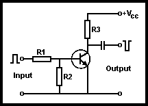
The Class C amplifier leads straight into the use of the transistor as a switch. In this case the criterion becomes 'is the transistor conducting or not?'. This is the basis of digital circuits, ie ON or OFF; no intermediate state is wanted. The Class C amplifier is also representative of a transistor switch circuit, as shown in Fig 3.28.

Fig3.28.Typical transistor switch circuit
The operation of the circuit is similar to that of the Class C amplifier, however, the input is usually a rectangular pulse and not a sine wave. The resistor R2 keeps the transistor in a non-conducting state and R1 purely limits the base current. If the input signal exceeds 0.6V (assuming a silicon transistor) the transistor suddenly conducts and the output voltage, because of R3, drops to a low value, ie the signal is inverted. When the input falls to less than 0.6V then the transistor will no longer conduct. The collector resistor R3 could be replaced by a lamp or relay so that when an input signal is present current flows and the relay operates or the lamp lights. With no input signal the transistor will conduct. Such a circuit is commonly used where remote switching is needed - for example a small switch on a control panel may remotely activate an antenna changeover switch inside a transmitter.

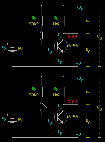
This animation shows the transistor used as a switch.
Normally the switch in the above diagram would be replaced by a voltage from a preceding circuit, but for simplicity a switch replaces this. With the switch closed, the output goes to zero volts, with the switch open it rises to the full rail voltage (5V). The transistor is either on or off, conducting or not conducting, just like a switch.