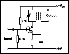
If the collector resistor of an amplifier is replaced by a parallel-tuned circuit, an amplifier can be created that will only amplify a selected range of frequencies. A typical circuit is shown in Fig 3.29.

Fig3.29.Typical tuned amplifier circuit
From earlier theory in Chapter 2, we know that the dynamic resistance (impedance) of the parallel-tuned circuit is a maximum at resonance. Maximum output of this circuit will occur at this point. Higher or lower frequency will give reduced output, ie maximum amplification occurs only at the resonant frequency of the tuned circuit.
If the parallel resistance across a tuned circuit decreases, then this lowers the dynamic resistance and so degrades the performance of the tuned circuit, widening the band of frequencies amplified. The input impedance of a following circuit appears across the tuned circuit. To minimize this degrading of the amplifier response, the output is usually taken from a secondary winding close to the tuned inductor in the collector circuit, ie it becomes a transformer with an untuned secondary winding (see Chapter 2).
If in Fig 3.29 the bias on the transistor is changed to Class C, the collector current is distorted and contains second and third harmonics. Thus, if the tuned circuit is resonated at one of these, the circuit would operate as a frequency multiplier. Such a circuit, as a frequency doubler or tripler, is often found in multi-band radios.