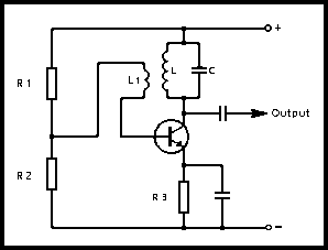
At some point in a receiver or transmitter it is necessary to produce a continuous sine wave. This is accomplished by a circuit known as an 'oscillator' and Fig 3.30 shows a basic circuit. The tuned circuit L-C determines the frequency of oscillation; the two coils L and LI form the primary and secondary windings of a transformer; resistors R1, R2 and R3 set the bias conditions. The circuit is similar to a common-emitter amplifier that produces a 180° phase shift between input and output voltages.

Fig 3.30. Basic oscillator circuit
When the circuit is switched ON there is a momentary surge which causes the circuit L-C to try to oscillate. This signal is fed back by the transformer action of L and L1. The phasing is such that this will cause a signal at the collector which adds to the original and so increases it. This is known as positive feedback. The signal is fed back again in the correct phase and so oscillations are maintained. Thus the principle of the oscillator has been established.
Oscillators are amplifiers in which there is intentional positive feedback from the output to the input. This feedback can be achieved in several ways, and hence there are various oscillators, usually named after their originator, eg Colpitts, Clapp-Gouriet, Hartley, Vackar, etc. The first two are the most common in amateur radio. In general there is little to choose between them.
When one end of the tuned circuit which determines the oscillator frequency is earthed, it can be replaced by a quartz crystal, hence the 'crystal oscillator'. The oscillator frequency is now determined by the crystal and the frequency stability is therefore very much higher, but the oscillator cannot be tuned (see Chapter 2).