When the amateur signal is adequately free of all unwanted outputs, any problems which occur are usually due to the inability of the equipment affected to operate in the RF fields generated by the transmitter. It is perhaps not too surprising that, unless the manufacturer has provided the necessary safeguards, circuits which are designed to work at mill-volt or milliamp levels (or even less) are adversely affected when signals maybe 1000 times stronger are present. However, in today's dense electromagnetic environment, such safeguards should be included in all electronic equipment. Interference falls mainly into the following categories:
(a) Direct reproduction. The frequency of some amateur signals is within the pass-band of certain stages. If the amateur signal enters one of these stages it is simply added to the wanted signal. For example, the 1.8, 3.5 and even the 7MHz band may affect the video frequency circuits in TV sets and video recorders (often causing finely spaced diagonal bars on the picture). A 3.5MHz transmission may enter the colour circuits centred on 4.43MHz (the picture sometimes reverts to black and white when the receiver is affected). The 10MHz band is close to the FM radio IF on nominally 10.7MHz. Note that in many cases a relatively low level of unwanted signal flowing in the circuit may produce a significant amount of interference.
(b) Harmonic generation. This normally requires a somewhat higher level of unwanted signal to be present in the affected stages, ie sufficient to over-drive the circuit so that it becomes non-linear. Harmonics can be generated in RF and IF amplifiers, mixers etc (particularly in TV and radio tuner stages). The effect is similar to that when the amateur signal itself contains harmonics.
(C) Cross-modulation, desensitising and blocking. Again this is an effect of relatively strong signal pick-up and subsequent non-linearities. The presence of the unwanted signal causes the gain of the affected stage to change (usually it is reduced). Variations of the level of the unwanted signal - such as occur when transmitting SSB, AM or even CW (A1A mode), are therefore impressed on the affected signal. This can be very disruptive. This effect is less noticeable where the transmission amplitude is constant (eg FM).
(d) Rectification (detection, demodulation etc). As with (b) and (c), non-linearities are responsible. The problem is most noticeable in audio circuits where the base-emitter junction of a bipolar transistor (either as a discrete device or as part of an integrated circuit) acts as a rectifier when strong RF signals are applied to it. Again, SSB, AM etc arc more troublesome than FM. A good example of this is when the voice of an amateur transmitting in the AM mode appears through the loudspeakers of a neighbour's hi-fi.
(e) Timing errors. Sometimes it is the timing and sequence of signals which enables a circuit to operate correctly. In this category are digital circuits, TV time-bases etc. Usually the signals are pulses of several volts in amplitude, so the circuits are relatively immune to RF breakthrough provided that this is below a certain level. However, above this level the timing may be upset by the RF signal superimposed on the pulse waveform, and this will cause the circuit to perform incorrectly. For example, the time-base circuit may fail to trigger correctly, causing the picture to 'tear' or roll. Circuits involving microprocessors and computers may fail to carry out the expected control functions etc.
The three main routes are direct pick-up, pick-up via connecting leads, and indirect pick-up. Take, for example, a tape recorder which, while running on batteries alone (with no mains lead), suffers breakthrough. This is probably a case of direct pick-up in the circuitry. Apart from moving it around the house to try to find a place where the field strength of the amateur transmission is lower, or carrying out modifications to the recorder itself, there is probably little that can be done to cure the problem.
If the breakthrough only occurs when the mains lead is plugged into the recorder, and ceases when it is disconnected, this is generally a good sign. It means that the problem can probably be cured by fitting a filter or ferrite ring choke in the lead.
Indirect pick-up is more difficult to diagnose and to cure. The recorder may be satisfactory when running from batteries, but the interference starts even when the lead is brought near it, before it is actually plugged into it. It is obvious that fitting a filter in the lead will probably have little or no effect. One method of dealing with this problem is dealt with later.
On the lower-frequency bands, the unwanted signal is most likely to be picked up and fed to the affected equipment via the leads connected to it. The cause of the interference may be the RF current flowing through the circuit or, less commonly, the increased voltage field around the equipment. Both may occur at the same time. Longer leads generally mean more pick-up. Even when the RF current passes only through the 'earthy' side of the circuit, this can create voltage differences within the circuit.
At the higher frequencies (particularly VHF and UHF), because parts of the circuit and the internal wiring are long enough to act as efficient receiving antennas, there is more danger of direct pick-up in the equipment itself.
In the UK, TV is broadcast only at UHF (470 to 860MHz). The TV antenna is too short to be an efficient 'receptor' on the lower-frequency amateur bands (i.e. below 30MHz). It is much more likely that pick-up occurs on the braid of the TV antenna downlead, which acts rather like an end-fed receiving antenna (typically about 30ft long). Strong RF currents enter via the 'outer' side of the TV antenna coaxial socket, flow through the set and into the mains wiring. Almost any part of the circuit may be affected. A conventional high-pass filter, fitted in the coaxial socket at the TV set antenna input, filters only those signals which are picked up on the antenna itself, so it will probably be ineffective. However, one of the braid-breaker circuits in Figs 9.3, 9.4 or 9.5 is much more likely to be successful. Occasionally a ring choke may be needed on the mains lead.
At frequencies above about 30MHz, the TV antenna becomes an increasingly efficient receptor of unwanted signals (especially on the 144 and 432MHz bands), while braid pickup problems tend to decrease. The tuner stage in the TV set may be overloaded. Self-generated harmonics usually affect only certain TV channels just as though the amateur transmitter was at fault (see examples given previously). However, in cases of cross-modulation (and where interference occurs after the tuner), it is usual for all the channels to be affected more or less equally.
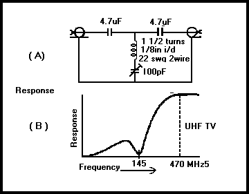
If it is the TV antenna which is picking up the unwanted transmission, a filter fitted at the antenna socket of the set should always be effective, provided that it has sufficient rejection on the unwanted frequency. For multi-band operation up to the 432MHz band the best choice is probably a good-quality UHF high-pass filter which has a sharp cut-off below 470MHz. However, if interest is concentrated on a particular band, a band-stop filter could be used. Fig 9.11 shows a simple circuit which is easy to construct and which can be aligned without test equipment.

Fig 9.11 A high-pass TV filter with increased rejection of a particular band of interest - in this case 144MHz
While some cases of interference are readily cleared by the fitting of a filter or a braid-breaker (sometimes both are needed), others can be more difficult. Braid-breakers and ring chokes will only block the interfering currents. Occasionally it is the RF voltage field introduced into the vicinity of the set- and not the current - which is responsible for the interference (ie an indirect pick-up effect). Indeed, blocking the current may actually increase the voltage - and the breakthrough. In such cases it may be better to fit the braid-breaker a short distance along the coaxial cable, away from the set (but not too far - l0ft maximum). Similar considerations apply to the positioning of a ring filter on the mains lead. All other nonessential conductors which may also be bringing interference to the set (eg a set-top lamp) should also be removed. If it is electrically safe to do so, connecting the braid of the down-lead to a reasonable RF earth will often help greatly by diverting the interfering signal away from the TV set.
Transmissions on almost any amateur band may break through on domestic radios. A classic case is 'image' or 'second-channel' interference (see Chapter 5) to medium-wave reception from l60m transmissions. For example, when trying to listen to 1053kHz (one of the frequencies currently allocated to BBC Radio 1), the following occurs:
Wanted mixer product - Local oscillator - Wanted frequency = IF 1508kHz - 1053kHz = 455kHz
Unwanted mixer product - 160m signal - Local oscillator = IF 1963kHz - 1508kHz = 455kHz
Even when operating on the higher frequency amateur bands, with some receivers there is still the possibility of interference to medium-wave reception (rarely to the long-wave). The receiver local oscillator often contains so many harmonics (in any case these will be produced in the mixer stage) and each time that one falls 455kHz away from an amateur signal, a 455kHz IF is produced.
A satisfactory cure would be to reject the amateur signal before it reaches the mixer, but in practice this is not normally possible. Most sets have no external antenna into which a filter (eg 1600kHz low-pass) could be inserted, and internal modifications would be a formidable task. However, it may be possible to reduce the interference by treating it as a case of direct pick-up, and keeping the radio away from wiring, piping (which may be increasing the strength of the interfering signal), by experimenting with its orientation etc. As the problem only occurs on certain 'spot' amateur frequencies, it may be no great inconvenience to avoid these at times when it is known that annoyance could occur.
VHF-FM problems may usually be treated by the same techniques as used for interference to television, provided that a properly installed Band 2 antenna is used. The band is from 87.5 to 108MHz. However, as the antenna is longer, it will pick up more HF amateur signal than a TV antenna. In equipment where the radio facility is part of a stereo hi-fl system, the possibility of RF breakthrough directly into the audio circuit must not be overlooked. This is dealt with later.
Self-generated harmonics which are troublesome are the third from the HF end of the 28MHz band (affecting 87.5 to 89.1MHz) and the second from the 50MHz band (affecting 100 to 104MHz). Usually only one programme is affected at any one time, depending on the amateur frequency in use.
Interference from the VHF amateur bands (where considerable antenna pick-up is likely) is also a problem. The major cause will be cross-modulation, and usually the whole band is affected. Braid pick-up may be cured by the braid-breaker circuits of Figs 9.3 or 9.4. For antenna pick-up, a suitable filter may be selected from the spectrum chart of Fig 9.1. To reject HF transmissions, a high-pass filter with an fc of 87MHz would be ideal, but one with an fc of 40MHz (originally intended for use with VHF TV sets) should also be effective. To reject a particular VHF or UHF amateur band, a band-stop filter could be used. However, a more universal solution would be to use a good band-pass filter which covers the whole of the FM radio band.
Some FM radios have antenna inputs designed for 300Ω twin feeder. In many cases perfectly satisfactory reception is obtained if 75Ωcoaxial cable is connected directly to such sets but, when additional filters are needed, it may also be beneficial to fit a 75 to 300Ω balun.
Audio hi-fl equipment often suffers from RF breakthrough, whether it incorporates a radio tuner or not. Although the screening, filtering, decoupling, earth paths etc in the equipment may be adequate for audio purposes, they are generally poor at RF. Sensitive audio amplifiers are easily driven into non-linearity by high level RF signals, and rectification occurs. With AM (A3E) transmission, the hi-fl owner will probably hear every word transmitted, and possibly at considerable volume. If it is SSB, only the characteristic 'quack quack' will be heard. With FM, there may only be a click when the transmission starts and finishes, and this may often go unnoticed. However, in cases of serious overload, the audio volume may decrease, or even be totally silenced.
Where the audio equipment consists of separate units, it is usually possible to filter the interconnecting leads, but when it is one integrated system, such possibilities are limited. Where the leads are accessible, using the ferrite ring choke technique to block longitudinal unwanted RF currents is often effective.
In stereo systems, the loudspeaker leads are frequently the cause of the trouble. They form a dipole antenna which is only too efficient at picking up radio transmissions, and may even resonate on some amateur bands. Strong RF currents are fed through the audio amplifier, and these affect particularly the negative feedback circuits. A ring choke inserted in each lead close to the amplifier speaker output socket is often very successful. It may also be useful to fit a decoupling capacitor of 1000 to l0,000pF (1 to l0nF) across each lead at the connecting plug. In difficult cases, screened speaker leads may be necessary.
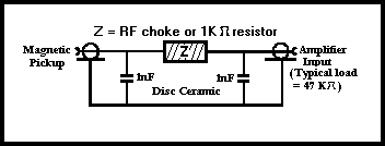
Sometimes conventional filtering may be necessary to remove the RF interference picked up, for example. by a magnetic pick-up in a record turntable unit. As this has a low level AF output (a few milli-volts) and requires considerable amplification, it is rather susceptible to such problems, especially from VHF transmissions. Fig 9.12 shows a suitable circuit.

Fig 9.12. A low-pass filter to remove pick-up on a magnetic cartridge
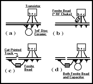
Although internal modification to any equipment is the responsibility of its owner and not the amateur, this may be necessary in stubborn cases of interference where internal pick-up is diagnosed. Fig 9.13 shows examples of RF filtering directly on the affected device.

Fig 9.13. Examples of internal filtering sometimes needed to cure stubborn cases of interference - especially from VHF and UHF transmissions. High-gain, low-level audio stages are particularly vulnerable
These have problems in addition to those suffered by TV sets. Most recorders incorporate a wideband antenna preamplifier which covers all UHF - and possibly VHF - TV frequencies. This may be susceptible to overloading by strong amateur signals (especially VHF and UHF). On replay, the high-gain video circuits which amplify the weak signals delivered by the heads may suffer from the lower frequency bands -particularly 1.8, 3.5 and 7MHz. Note that filters and braid-breakers may have to be fitted both to the antenna lead and the lead to the TV set.
These are sometimes used in areas of poor reception of TV and FM radio. They are normally fitted directly at the antenna, and powered via the coaxial downlead. Many cover the entire VHF and UHF spectrum, and some respond down to a few megahertz. Attempts to cure interference problems at the TV or radio will not be fully successful if interference which occurs because of amplifier overload is not dealt with beforehand. Normally, fitting a suitable conventional filter at the preamplifier input is effective but, as the antenna will probably be mounted in a well-elevated position, the practical problems of doing this are obvious.
It is becoming increasingly popular to amplify TV and radio signals, and then split them to feed several rooms in the house. As with masthead units, most systems are essentially wideband and are easily overloaded. The same treatment applies if access to the amplifier is possible. However, the use of multiple downleads may aggravate the effects of braid pick-up. When dealing with such a system, do not neglect to inspect the condition of any joints in the downleads. They are often installed by people who have no knowledge of RF and treat them as normal wiring. Unterminated branches may also give rise to problems, becoming tuned stubs at certain frequencies.
Interference to and from other equipment is a growing problem. The use of home computers and word processors is well established and interference problems with radio amateurs do occur, both in the form of breakthrough into the computer, and of signals radiated by the computer which can interfere with the amateur's reception. Troubles may be minimised by fitting ring chokes (or some form thereof) to the mains leads, and especially to the leads interconnecting the peripheral units. Also check that the casing screws on the computer's case are tight and that the removable panels make good electrical contact with the rest of the unit.