Fig 2.17 shows the basic frequency responses of two commonly used filters: the low-pass and the high-pass. Fig 9.2 shows the characteristics of two others: the band-pass and the band-stop. The purpose of a filter is to pass the wanted frequencies and reject the unwanted. The type most suitable for a particular application may be determined from the spectrum chart shown in Fig 9.1. For example, to prevent the harmonics of a multi-band HF transmitter (1.81 to 29.7MHz) from causing interference to broadcast VHF-FM radio, UHF TV and other VHF/UHF services, a low-pass filter (LPF) with a cut-off frequency of 30MHz is often inserted in the feed to the transmitting antenna.
Where a UHF TV set is experiencing breakthrough from, say, strong local 144MHz transmissions, a high-pass filter could be fitted in the receiving antenna coaxial downlead (usually at the antenna 'input' socket). However, for problems with HF transmissions, a 'braid-breaker' is more appropriate. This is discussed later.
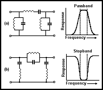
Fig 9.2. Examples of circuits and frequency response curves of (a) a band-pass filter, (b) a band-stop filter
Band-pass and band-stop filters also have their applications where a single-band transmitter is used, a band-pass filter in the antenna feed will pass the wanted frequency, but remove unwanted signals both above and below it. A band-stop filter does the opposite. It could be used in the radio or TV downlead to protect the set from the strong signal radiated by the transmitter because it operates over a relatively narrow frequency range.
All filters introduce some insertion loss at the frequency of the wanted signal, and it is an important design parameter that this loss should be acceptably low (ie less than 1dB). The sharpness of the transition between the pass-band and the stop-band (and how well it rejects an unwanted signal which is close to the wanted one) depends upon the complexity of the circuit. For example, if the simple HPF circuit of Fig 2.l7(b) had a cut off frequency of 470MHz (for passing UHF TV signals), it would give little protection against transmission on 432MHz.
Another important filter parameter is its characteristic impedance. A filter inserted in a 50Ω feeder should, inside its pass-band, appear simply as another piece of 50Ω feeder, ie it should match the feeder's characteristic impedance. The match may not be perfect, but a good filter will exhibit a low SWR ie 1.2:1 or less. A mismatched filter will have a high SWR, high insertion loss and often a degraded stop-band.
The ferrite ring choke is one electrical component which find frequent application in the fight against EMC problems. In the transmitting station, it may be used to block the flow of RF currents (for example, into the mains wiring or on the braid of the antenna feeder) which, if unsuppressed, would increase the local field strength. It may also be similarly used with the affected equipment in order to block RF currents which would otherwise flow along leads and into the equipment.
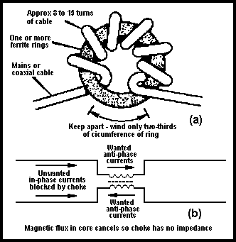
Fig 9.3. (a) Winding details of a ferrite ring choke for use as a mains filter or as a braid-breaker in a TV or FM radio coaxial downlead. (b) How it behaves electrically
Fig 9.3 shows how a choke should be constructed. The main requirement is that it have sufficient inductance at the interfering frequency. However, to maximise the self-resonant frequency, an excessive number of turns should be avoided, and the start and finish of the windings kept apart. A correctly made choke is usually effective over a wide frequency range.
Unwanted signals which are picked up on leads usually flow together (ie 'in phase' or 'longitudinally') along all the wires comprising the lead. The wanted signal currents flow in anti-phase, and are not affected by the choke. It can therefore be used as a 'braid-breaker' which blocks interference picked up on the braid of a TV or FM radio coaxial downlead, as a mains filter on a twin or three-wire lead, on audio and video screened or balanced twin leads etc.
There are alternative forms of the choke, such as a two-part core and clamp, a long ferrite rod (with many turns) or even a non-inductive former (eg a plastic tube), provided that sufficient inductance can be obtained.
The simplest, but by no means least effective, mains filter is the ferrite ring choke of Fig 9.3. If it is sufficiently thin and flexible, the mains lead itself can be wound on the ring. With more rigid cable, fewer turns may be used, but with several cores stacked together to maintain the inductance.
Certain commercial units (electric motor interference filters, 'mains conditioners' for computers etc) are designed primarily to suppress transients between the live and neutral conductors. Many have a common earth connection between the input and output terminals through which interfering currents can pass without being filtered. These can be used only where the earth continuation is not required, or where it can be choked separately, using a wire gauge which is sufficient to carry full fault-condition currents.
The purpose of a braid-breaker is to block unwanted currents which result from RF pick-up on the braid (outer screen) of a coaxial cable (eg a TV antenna downlead). Again, the ferrite ring choke of Fig9.3 is ideal for this purpose, wound using the cable itself, or, if this is too rigid, with miniature coaxial cable fitted with suitable mating connectors. The wanted signals picked up by the antenna propagate in the downlead in anti-phase, and are not affected by the inductance of the choke. The insertion loss is negligible, even at UHF TV frequencies.
Another method of braid-breaking is a 1:1 ratio RF transformer as in Fig 9.4. This will only pass the wanted anti-phase signal. One method of construction is to use two tightly coupled windings (usually twisted together) on a small ferrite ring or bead. Another is the 'Faraday loop' method, using two loops of coaxial cable taped together. However, great care must be taken to prevent excessive signal loss at higher frequencies. Home-constructed units will probably be unsuitable for UHF TV.
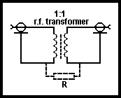
Fig 9.4. Braid-breaker using a 1:1 ratio transformer which can only pass the wanted anti-phase currents. R is a static discharge path -10KΩ or greater
A third type of braid-breaker, primarily designed to protect UHF TV reception, is shown in Fig 9.5. Its operation is essentially different from the other. It consists of a balanced HPF with a cut-off of 470MHz, but performs satisfactorily in the unbalanced coaxial downlead. The low-value coupling capacitors have a high impedance at lower frequencies, and therefore block the unwanted RF currents.
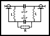
Fig 9.5. UHF TV braid-breaker using balanced high-pass filter technique. This circuit also attenuates interfering signals picked up on the antenna below 470MHz. L is 4 turns 22swg 5mm i/d. R is a static discharge path - 10kΩ or more
Because the amateur station is likely to be in close proximity to domestic electronic equipment, it is in his interests to minimise the possibility of EMC problems.
The amateur must obviously ensure that the levels of unwanted emissions from his station are acceptably low. However, even if the problems are due to inadequacies in the domestic equipment, it is desirable to try to design the station and antennas so as to keep the regions of high radiated field strength as far as possible from other domestic premises. While this is not always easy, it has a number of benefits. It minimises the chance of interference to domestic equipment, and of the station picking up noise from domestic equipment. It also improves the performance of the station - high field strengths in adjacent premises not only give rise to EMC problems, but also waste power that should really be going out to distant parts of the globe!
Particular attention should be paid to the type and location of the antenna, its feeder and how the station is earthed.
Fig 9.6 shows an amateur station designed for good EMC. Each part will be considered in turn.
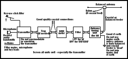
Fig 9.6. Example of station format required for good EMC
Transmitter design which minimises harmonic and other unwanted outputs is dealt in Chapter 8. Because the higher harmonics usually fall off in level (see Fig 8.4), the UHF harmonics which are radiated by a well-designed HF transmitter are rarely responsible for television interference (TVI). Much greater attention must be paid to VHF and UHF amateur transmissions. For example, the fourth harmonic from the 144MHz band falls in channel 34 (575.25MHz vision, 581.25MHz sound) and the fifth in channels 52 (719.25/725.25MHz) and 53 (727.25/733.25MHz). However, unless the harmonics are particularly strong, this problem is likely to be apparent only in those areas where one of these channels is allocated.
The FM radio band (87.5 to 108MHz) may suffer from certain harmonics, particularly from the HF end of the 28MHz band (the third falls between 87.5 and 89.1MHz) and the new 50MHz band (where the second falls between 100 and 104MHz). There is also some possibility that strong third harmonics from the 3.5MHz band could affect the 10.7MHz IF stages in the radio. Harmonics are not the only problem. Most transmitters use frequency multipliers or mixer circuits, and the output may contain certain signals having no harmonic relationship to the actual output signal (see Chapter 8). These too must be well suppressed.
Many transmitters claim, or in reality actually achieve only 40-60dB of harmonic suppression, with other unwanted signals somewhat better. The ATU and antenna will provide some further attenuation. While this may be adequate in many circumstances, in some cases additional attenuation will be necessary. Usually this can be achieved by inserting an appropriate filter in the feed to the antenna system.
The effectiveness of additional filtering can be seriously impaired if unwanted signals are allowed to leak out of the transmitter. While the signal which is fed to the antenna may be 'clean', the signals which leak out may cause persistent and apparently incurable, interference problems. Serious attention should be paid to the effectiveness of the screening inside the transmitter and of the case, and of the decoupling and filtering of the power, key, microphone and any other leads connected to the transmitter. These must not be allowed to carry RF energy from inside the case, and then allow it to be radiated.
A 'trap' is a simple stop or notch filter, often consisting of single resonant circuit. It is therefore simple to make and to tune to the correct frequency. It is not always necessary, but it is an easy way of providing an additional 20 to 30dB attenuation over a relatively narrow bandwidth - often very useful when a particular transmitter harmonic might cause problems. At VHF and UHF, a tuned coaxial 'stub' (usually λ/4 long) is often used. Unless it is compensated, a trap may cause some mismatch. This is usually small, but to prevent permanently high SWR readings, it is best to locate it before the SWR meter.
The SWR meter is described in Chapters 7 and 10 - in particular, see Fig 7.10 and associated text. With some designs, the sensitivity varies with frequency. With others, is essentially constant over a wide frequency range, and this type is usually calibrated to measure RF power. Some meters will read peak envelope power (PEP) and are convenient for SSB measurements. The SWR meter enables impedance match of the antenna and feeder system to be checked, or for the ATU (if used) to be adjusted for minimum SWR at its input, thereby presenting the filter with the correct load impedance at the transmitting frequency. The meter must be designed to operate with the same impedance as the filter (usually 50 or 75Ω. The positions of the SWR meter and filter could be interchanged but, as the meter uses diodes to rectify a sample of the RF signal passing through it, these may generate some low-level harmonics. It is therefore better to place it before the filter, which will then remove the harmonics.
At HF, where operation usually takes place on several bands, it is common practice to use a low-pass filter with a cut off frequency of 30MHz. While this will not reject unwanted signals below 30MHz, it does protect the VHF radio band, and other services which might be affected even by low levels of unwanted signals. A few mill-watts at VHF can cause a surprising amount of interference over a wide area.
At VHF and UHF, although a few transmitters do cover more than one band, each band usually has its own antenna and feeder. While low-pass filters could be used, it is just as convenient to use a band-pass filter for each band. This will remove unwanted transmitter outputs either side of the amateur band. It will also help on reception where very strong radio transmissions from other services sometimes cause overload problems to sensitive amateur receivers.
Strictly speaking, an ATU is a matching unit rather than a tuning unit, as explained in Chapter 7, it is also known as an 'antenna system tuning unit' (ASTU) . Opinions differ as to whether an ATU is necessary in situations where the antenna and feeder system presents the correct 50 or 75Ω impedance required by the transmitter, SWR meter and filter. However, the 30MHz low-pass filter in an HF station will not remove those transmitter harmonics which fall inside its pass-band, eg when operating on 14MHz and below. It is unlikely that the harmonic suppression of the transmitter alone will exceed 50dB. Depending on the type of circuit used, an ATU can give some useful additional attenuation of these harmonics and of other unwanted outputs.
If the ATU circuit is such that the output is inductively coupled, the antenna and feeder system can (if required) be isolated from the rest of the station equipment. If twin feeder is used, the ATU performs the function of a balun (see later). If coaxial cable is used, the screening braid can be earthed either to the equipment earth or to a separate RF earth, as required. If the ATU feeds directly into an end-fed wire (note that this is not recommended) it enables the RF earth return to be kept quite separate from the mains earth. Fig 9.7 shows an example of this situation.
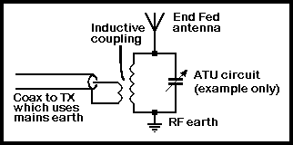
Fig 9.7. Use of Inductively coupled ATU circuit to enable the RF and mains earths to be separated. Note that the RF earth is part of the antenna system and carries all the antenna current
While it is the RF current flowing in the antenna which is responsible for true electromagnetic waves, those parts of the antenna which are at a high RF voltage will produce a strong, localised voltage field. This can transfer the transmitted signals into nearby equipment and wiring because of the effects of capacitive coupling. Similarly, those parts carrying high currents may cause considerable inductive coupling. To minimise the problems that may result, the antenna should be situated as far away as possible from buildings and from any overhead mains and telephone wiring running outside, even if this means using a somewhat longer run of feeder. A relatively small increase of distance can result in a considerable reduction in the level of pick-up of the amateur signal (see Chapter 7).
Where a high-gain beam antenna is used (particularly at VHF and UHF), avoid situations where it will 'fire' straight into a house and the electronic equipment inside it. Mount the antenna as high as local planning regulations allow, so that it beams over the rooftops and, if possible, over neighbouring receiving antennas. Note that is often difficult to cure problems which are due to direct pick-up in the affected equipment, but relatively easy if the pick-up is on the antenna itself.
Antennas most likely to increase breakthrough are those which are indoors, cross over the house, or are end-fed directly from the house. These are not recommended. If the transmitting equipment is above ground level (the spare bedroom is a popular location), do not forget that the RF earth return for an end-fed wire actually forms part of the antenna system, and will radiate strongly. Fig 9.8 shows a typical domestic situation where an end-fed wire is used. This may be satisfactory for receiving, but could cause problems when transmitting.
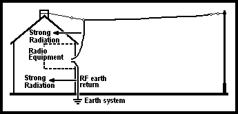
Fig 9.8. Typical end-fed wire antenna (often used by short-wave listeners). This results in strong radiation into the house and can cause problems when transmitting.
A horizontal, balanced antenna (eg a λ/2 dipole) will usually produce a lower field strength around the house than an end-fed wire. It should be fed with balanced (twin) feeder or, if the feed impedance is suitable, with coaxial cable via a balun (balance-to-unbalance transformer) at the centre of the antenna (see Chapter 7). Although a dipole will work without a balun, a considerable amount of RF current will flow back from the antenna on the screening braid of the cable, causing it to radiate strongly. To make matters worse, the cable is usually connected through the station equipment to the mains safety earth. The braid current will therefore flow into the mains wiring, and re-radiate the signal throughout the house, and possibly into neighbouring properties.
To prevent the signal which is radiated by the antenna from being picked up by the feeder and fed back to the house, the feeder should drop at right angles away from the antenna for as far as possible. It should not be pulled tight so that it runs close to, and under, one 'leg' of the dipole, as in Fig 9.9(a). Coaxial cable (and also screened twin, which is rarely used by amateurs) has an advantage over unscreened feeder because it can lie in contact with the ground, be buried and (if possible) earthed, as shown in Fig 9.9(b). This ensures that no current is fed back.
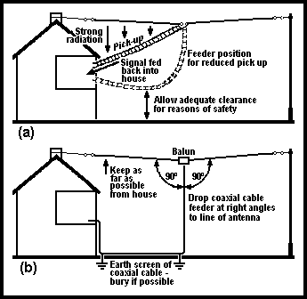
Fig 9.9. Prevention of pick-up of the radiated signal by the feeder; (a) by maximising the distance between antenna and feeder; (b) by earthing the coaxial screen
If it is essential to use an end-fed antenna, do ensure that the RF earth and the domestic mains earth are kept separate. Operating at ground level from a remote outbuilding (such as a garden shed) allows short, direct earth connections to be made. An alternative is to use an earthed coaxial cable to feed the antenna, as shown in Fig 9.10, although matching at the antenna feed point (especially if several bands are used) does require some ingenuity. A remote tuning unit is one solution. Another is to use a trap monopole antenna, ie one half of the trap dipole in Fig 7.13, or a variant of it.
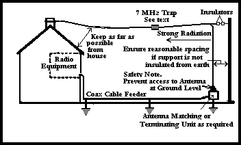
Fig 9.10. End-feeding an antenna while maximising EMC. Although less convenient than Fig 9.8, this method causes far fewer interference problems.
If the problems still persist after taking steps to optimise the design of the station, it may be helpful to come to some acceptable agreement to operate only at selected times or at power levels where the problems do not occur, while efforts are made to diagnose and cure the problem at the affected equipment.
EMC problems tend to appear or vanish with relatively small changes in power level, and it may be that a slight reduction of power will avoid most of the problems. Problems can also be minimised by being more flexible in choosing power levels. It is not necessary to use as much power for cross-town contacts as for working long distances.
For this reason, a speech processor can be of great help. particularly on SSB. It increases the average value of the speech waveform while keeping the peaks to a predetermined maximum. This produces a more 'punchy' signal which can provide some of the benefits of higher output power without the EMC problems.
If interference persists after all reasonable efforts have been taken to maximise the EMC of the station, then attention must be paid to the affected equipment and its installation conditions.


