The closing down of the UK VHF 405-line TV service has removed what was probably the most common reason for complaints of amateur interference, ie harmonic problems with HF band transmissions (both radiated by the transmitter and self-generated in the TV set itself). However, the growth of mobile and other radio services on the vacated TV (and other) frequencies means that high standards for unwanted transmitter outputs must be maintained. There is a good chance that an amateur will live close to users of VHF and UHF services (even next door), and very low levels of unwanted outputs could cause severe interference. Harmonics which fall below about 30MHz may not be as troublesome because users of HF are relatively few and hence likely to be more remote. With the relatively high levels of HF background noise and interference, low levels of unwanted signals will probably go unnoticed.
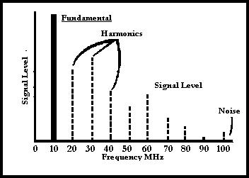
Without attention to filtering there is a progressive (if somewhat erratic) drop in the level of the higher harmonics. Fig 8.4 shows the comparison of harmonic levels of a 10MHz transmitting station, illustrating the improvement obtained by good station design. Harmonics from the lower frequency amateur bands may fall within a higher band (eg 2 x 3.53MHz = 7.06MHz, thus interfering with other amateurs) or outside the HF end (eg 2 x 3.7MHz = 7.4MHz, thus interfering with other services). Interference may involve TV or FM radio, leading to complaints from neighbours, eg 5 x 144MHz = 720MHz. This is within TV Channel 52. Further examples are given in Chapter 9.
Harmonics occur because amplifiers are to some extent non-linear, ie they distort the signal waveform. They are produced mainly in the high-power stages in a transmitter, especially those which use Class C amplification. This may be the most efficient, but it is highly non-linear. Even the relatively linear Class A and Class B amplifiers used in SSB transmitters are by no means harmonic-free. Most transmitters with a tuned PA stage use 'pi-network' output tuning (or some form thereof, such as 'L-pi'). Fig 4.9 is a typical example. This acts as a built-in low-pass filter and greatly reduces harmonic levels. In those transmitters where wideband (untuned) power amplification is used, different bandpass or low-pass filters are often used (being selected as required by the transmitter band switch).

Fig 8.4. Example of harmonics received from a 10MHz station. With poor station design, harmonic levels may be excessive (shown dotted). With good design It will be difficult to detect even the 2nd or 3rd harmonics above the received general noise level
Provided that the transmitter is fully screened and all the leads entering or leaving the case are fully filtered and decoupled, then harmonics should be no problem. As the only way out for RF signals is via the antenna socket, then any harmonics can be removed by a suitable filter fitted in the feed to the antenna system (see Fig 9.6). However, filtering is made easier if the production of harmonics is minimised in the first place by (for example) avoiding unnecessarily high drive levels in power amplifiers. Stages carrying RF signals should be individually screened and their power feeds well decoupled in order to prevent RF signals and harmonics from being carried around inside the transmitter via the internal wiring. A good-quality metal case which has no large holes, gaps or slots (which will allow RF leakage) will then complete the task of screening the transmitter.
Amplifier stages have an unfortunate tendency to oscillate if there is sufficient (unintentional) feedback from output to input. The presence of such spurious oscillations in some part of a transmitter circuit may result in radiation on essentially unpredictable frequencies in addition to - and possibly as powerful as - the wanted frequency. This may result in severe interference to other radio users over a wide area.
In many respects the techniques of filtering, decoupling, screening etc. intended to minimise harmonics, also help to prevent spurious oscillations. However, some additional precautions may be necessary. Note that if particularly violent oscillations occur, some transistors (especially the more expensive devices used at VHF and UHF) may be instantly destroyed. Take great care when investigating oscillations. It is wise to operate the suspected stage at a reduced voltage and with some current-limiting resistance in series with the DC supply.
'Self-oscillation' may occur at or near the working frequency of a stage, especially if both input and output are tuned to the same frequency. It may occur only when no RF input drive is present, eg between words on SSB or with key-up on CW. Its frequency will be fairly unstable and the transmitter may continue to give a noticeable RF output when the power level should read zero. Conversely, the oscillation may occur only when the stage is being driven. The result may be burbly, splashy speech and a rough CW note, with chirps and key-clicks. The cure for this problem is to minimise the feedback by ensuring that input and output circuits are screened from each other. DC feeds may also provide another feedback path and should be adequately decoupled. There may be enough feedback through the amplifying device itself to cause oscillation, in which case the stage will have to be 'neutralised'.
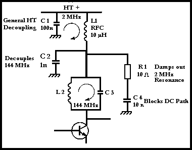
Oscillations may also occur at relatively low frequencies and sometimes modulate the RF signal, appearing as side-bands (often multiple) either side of the wanted output frequency. They may be the result of instability in audio stages or in regulated DC power supplies (often at ultrasonic frequencies) or by the chance resonance of RF chokes and decoupling capacitors, often in the DC feeds to certain stages. For example, VHF transistors often have a very high gain at much lower frequencies, and care must be taken to ensure that the decoupling of the DC supplies is effective at these low frequencies. Fig 8.5 shows how a 'hidden' parallel resonant circuit exists. To prevent the danger of oscillations the resonance must be damped, either by using a very-low-Q (ie 'lossy') choke for L1 or by adding R1 and C4 to the existing circuit.

Fig 8.5. Damping a hidden 2MHz resonance in a VHF amplifier circuit
VHF and UHF oscillations may occur in HF transmitters because of a poor choice of circuit layout, and the type and style of components used. This often results in capacitor leads, earth returns and other interconnections which are rather long, and are therefore somewhat inductive. Coils also may have long leads which are not part of the winding. These small, unintentional inductors have no adverse effect at HF, but form resonances at much higher frequencies with the stray capacitances in the circuit. Indeed, these 'parasitic' resonances may affect even well-laid-out circuits where lead lengths cannot be shortened and the correct style of components are used. As with low-frequency resonances, the cure is to make these resonances well damped. Low-Q VHF chokes (eg coils wound on resistors or on lossy ferrite beads) may be added at suitable points in the circuit to break up the parasitic resonances.
Many transmitters use mixing processes to obtain the required output frequency - especially for SSB and VFO controlled VHF transmissions. Mixers (frequency changers or converters) produce not only the wanted sum or difference frequencies (see Chapter 2) but also a whole range of undesirable signals. Most significant are harmonics of the local oscillator injection and harmonic mixing products, ie outputs created when the self-generated oscillator harmonics mix with the input signal to produce a large number of sum and difference signals.
For example, an SSB signal generated on 9MHz may be converted for transmission on 14MHz by using a VFO on 5MHz (9MHz + 5MHz = 14MHz). Unfortunately the mixer is likely to generate the third harmonic of the VFO on 3 x 5MHz, ie 15MHz. It may also generate the fifth harmonic, which will mix with the 9MHz and appear at 16MHz (5 x 5MHz - 9MHz = 16MHz). Considerable filtering will be needed to ensure that these unwanted products are sufficiently reduced in level by the time that they reach the transmitter output. Balanced and double-balanced mixers help to reduce such problems because if the balance is perfect, the oscillator signal and its harmonics do not appear at the mixer output.
Unwanted mixer products may be minimised as follows.
Modern commercial transmitters rarely use the low-frequency VFO and frequency multiplier system. Instead, a phase-locked loop (PLL) frequency synthesiser replaces the VFO and may operate at very much higher frequencies where a VFO would be far too unstable.
Synthesisers contain a crystal oscillator (typically 1 to 15MHz), voltage-controlled VFO (VCO) and digital divider circuits. There are often additional circuits such as frequency multipliers and mixers. The synthesiser circuit must be adequately screened and filtered to ensure that it does not radiate into, or pick up from, other parts of the transmitter. This could result in the transmission of signals on some very unexpected frequencies. An important failsafe design feature of a synthesiser is that the transmission must be inhibited if the VCO has not locked to the reference frequency. This prevents the radiation of a very unstable signal (albeit only momentarily, under normal working conditions).

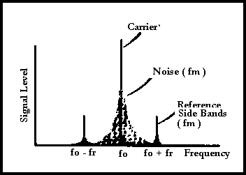
Fig 8.6. Spectrum of PLL frequency synthesised signal. With VHF and UHF transmitters, fr is often equal to the channel spacing, and sidebands (fo - fr) and (fo + fr) fall on adjacent channels. Good design minimises both noise and reference sidebands
Even the wanted output signal can be troublesome if the design does not minimise unwanted frequency modulation by noise (inherently greater than with a VFO or crystal oscillator) or by the reference frequency. This is often the smallest frequency step available and in channelised equipment (as used at VHF and UHF) is typically 12.5kHz or 5kHz. Fig 8.6 shows the spectrum of an otherwise unmodulated signal which could give rise to complaints of 'hash' or 'whine' on adjacent frequencies. Note that when modulated, the whole signal (and not just the carrier) will carry modulation sidebands, giving the distinct impression that the signal is being over-modulated.