On the crowded amateur bands, the amateur must ensure that he does not make excessive use of the space available by limiting the bandwidth of his transmissions to the minimum necessary for effective communication.
A signal which consists only of a single carrier wave occupies no bandwidth. It also conveys no information. The information is conveyed by modulating the carrier, frequency modulation (FM) and amplitude modulation (AM) being the most popular modes used by amateurs. Morse and single-sideband transmissions are both forms of AM. Modulating the carrier produces sidebands (see Chapter 4) and it is really these which contain the information. The complete transmission therefore occupies a band of frequencies.
Most amateur speech transmissions use single sideband (SSB, mode J3E) or FM (mode F3E). Ordinary AM (A3E mode) is rarely used these days. All may occupy a considerable bandwidth unless certain precautions are taken. Any attempt to transmit high-quality audio (which contains frequencies up to 15kHz) will result in the use of excessive bandwidth, and result in 'splatter' across adjacent channels. A frequency range from 300Hz to a top limit of 2.5 or 3kHz provides adequate intelligibility for communication purposes.
In AM transmissions, the bandwidth which should be occupied is twice the highest audio frequency, eg 2 x 2.5kHz = 5kHz. The transmitter audio stages should be designed to have an overall low-pass characteristic with a sharp cut-off above 2.5kHz. However, severe splatter will result if the carrier is 'over-modulated'. This occurs when too much audio signal is applied to the carrier, resulting in breaks during the modulation (see Fig 4.12). Too little audio makes the signal appear weak, so to ensure maximum intelligibility the modulation should be kept close to 100%. It is advantageous to use some form of automatic audio compression or limiting circuit which, when adjusted correctly, ensures a consistently high level of modulation but prevents over-modulation. Such a device is known as a "speech processor".

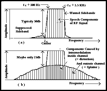
Fig 8.1. Spectrum of an SSB signal (a) when first generated; (b) after passing through an over-driven 'linear' amplifier
In SSB transmissions all the power of the signal is concentrated into one sideband only. Ideally, the unwanted sideband and the carrier would be totally suppressed and thus the transmitted bandwidth would be the same as that of the original audio modulating signal (ie somewhat less than half that required for AM). In practice the suppression is typically 50dB. The spectrum of an SSB signal is shown in Fig 8.1(a). It can be seen that the signal will occupy excessive space if the sideband suppression is insufficient. Poor carrier suppression may cause annoying heterodyne whistles to those trying to operate on adjacent frequencies.
Unlike AM (where it is normal practice to modulate the transmitter output stage), SSB is usually generated in an early stage and the required transmitter power obtained by using a 'linear' amplifier which should cause negligible distortion. However, if the amplifier is over-driven in order to obtain a power output of which it is not really capable, serious distortion will result. This causes intermodulation to occur. New unwanted signals are generated, both inside the transmitted channel (resulting in audible distortion) and outside (resulting in splatter across adjacent frequencies). The signal therefore occupies a greater bandwidth than before amplification, as shown in Fig 8.1(b). Over-driving can be prevented by the use of compression or limiting circuits, and these may operate either at audio or at radio frequencies.
When using FM. the audio signal deviates the frequency of the transmission from the nominal carrier frequency. This generates sidebands in a manner somewhat similar to AM. However, on FM an audio tone of, say, 2.5kHz creates sidebands not only at 2.5kHz, but also at harmonics of 2.5kHz (ie 5, 7.5, 10kHz etc). In theory these stretch to infinity each side of the carrier. In practice FM is not quite as anti-social as it appears, because the level of the additional sidebands depends greatly on the level of the modulating signal. They are negligibly small if the modulation index does not exceed about 0.6. The bandwidth is then comparable with an AM transmission. To achieve this, it is essential that the audio bandwidth and amplitude be kept within well-defined limits (probably even more so than with AM and SSB transmissions) and audio compression or limiting is used in almost every FM transmitter.
For amateur narrow-band FM (NBFM) the maximum deviation should not exceed ±2.5kHz. As well as causing severe splatter over adjacent frequencies, a very noticeable characteristic of over-deviated FM signals is that, even when correctly tuned in, the received audio sounds distorted on modulation peaks, and the receiver S-meter kicks noticeably downward. Even when the deviation is correct, the higher sidebands are not entirely negligible. To prevent out-of-band radiation, NBFM transmissions must not be less than 10kHz from the edge of the amateur band.
Morse (CW, A1A mode) is usually transmitted by on-off keying of an otherwise continuous wave, and is usually referred to by amateurs as CW. Methods of keying vary. In high-power transmitters, the supply current or a bias voltage in a low-power stage is keyed. In low-power transmitters the PA stage itself may be keyed. Whichever method is used, care must be taken to prevent key-clicks being produced.
Only a relatively narrow bandwidth is needed for morse -a few hundred hertz at the most at normal keying speeds. However, if the keying turns the transmitter on and off instantaneously, a signal with a very wide bandwidth is produced.
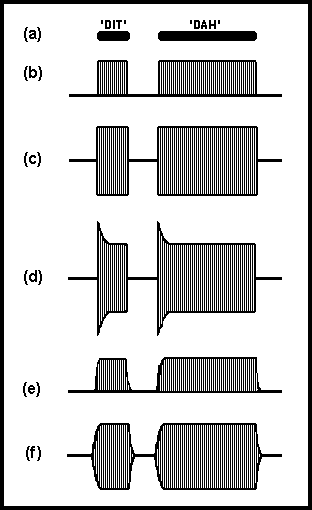
Fig 8.2 shows the transmission of the morse character 'A'. The instantaneous switching of the signal from zero to full power and back to zero is equivalent to 100% amplitude modulation by a rectangular-waveform audio signal. The sharp edges of the waveform produce sidebands which, on adjacent frequencies, are audible as clicks each time the key is pressed or released. The sharper the edge, the greater is the bandwidth occupied by the sidebands. Fig 8.2(c) shows the waveform without filtering, where the clicks may be audible over 100kHz away from the signal carrier frequency. However, although the keying may sound 'hard' (and probably rather tiring after some time), the disruption caused to users of nearby frequencies may not be realised by listening to the signal itself.

Fig 8.2. Comparison of keying wave forms with and without filtering. (a) The morse letter 'A'. (b) The supply current to the keyed stage without filtering. (c) The resulting RF signal envelope. Note the sharp edges. (d) The RF envelope when power supply regulation is poor. (e) The slowing of the rise and fall of the keying current using a key-click filter (see Fig 8.3). (f) The resulting RF signal envelope with soft edges and hence minimal key clicks
The situation is made worse if the transmitter PA power supply suffers from poor regulation and the DC voltage rises considerably during the key-up period. There is a surge of power at the instant the key is pressed, as shown in Fig 8.2(d). This accentuates the key-clicks and gives the received signal an unpleasant, thumping characteristic.
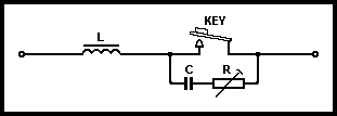
Key-clicks are suppressed by slowing down the rise and fall of the keying waveform, as shown in Fig 8.2(e). This in turn softens the transitions of the power output waveform, reducing the sideband spread and making the signal more pleasant to listen to. Fig 8.3 shows a simple filter circuit suitable for use where the key interrupts the DC current flow in a transmitter stage. When the key closes, the rise of current is slowed down by the inductor in series with the key. When the key opens, the fall of current is slowed down by the charging of the capacitor across the key. The resistor is necessary to prevent the rapid discharge of the capacitor at the instant when the key closes. Without it, sparking would occur at the key contacts.

Fig 8.3. Typical key-click filter. L serves to prevent too rapid a rise of current. C, charging through R, serves to continue the flow of current momentarily when key contacts open. Typical values: L = 0.01 to 0.1H, C = 0.01 to 0.1µF, R = 10 to 100 Ohm