The application of solid-state devices is almost endless. Individual devices such as the transistor and diode are called 'discrete semiconductors'. The following gives a sample of the uses and typical circuit arrangements. These are sufficient for the examination. However, there are many other arrangements and these can be found in many of the amateur radio handbooks available. Excessive power, voltage and/or current can easily damage all semiconductor devices. Power devices should be mounted on heat sinks - that includes diodes as well as transistors. Never impede the cooling process. That said, if used within their design limits, semiconductors are very reliable.
It is hard to define the difference between these two terms - usually 'diode' is used for low-power applications and 'rectifier' for higher-power mains applications. The silicon diode has now replaced the germanium diode for mains rectification. The germanium diode may still be found in signal-detection circuits where its low forward voltage drop is advantageous. The main use of the rectifier is in power supplies and is dealt with in Chapter 6.

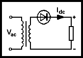
Fig 3.15. Use of the diode as a rectifier
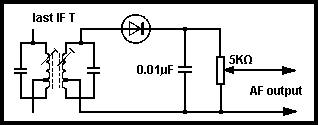
Fig 3.15 shows a typical use as a rectifier. It will produce half-wave rectification as indicated. The circuit of Fig 3.16 shows the typical use of the diode as an AM demodulator, the tuned circuit being the output from the final IF stage. A similar arrangement can be used to generate AGC voltages. The diode can also be used in FM demodulation (see Chapter 5).

Fig 3.16. Use of a diode as a demodulator
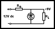
The basic arrangement is shown in Fig 3.17. The resistor RS is chosen so that when the load resistor RL is carrying its normal current, the voltage drop across RS will ensure that the diode is always operating beyond the knee of its characteristic (see Fig 3.5). If the output voltage tends to rise due to a reduction in load current, the zener diode will take more current from the supply and so keep the output voltage reasonably constant. The zener diode can also be used as a basis for more sophisticated power supplies (see Chapter 6).

Fig 3.17. Simple zener diode regulator circuit
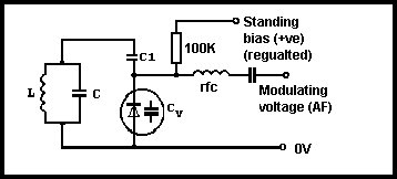
This is used where the frequency of a tuned circuit must be varied. Its use is mainly at RF frequencies. The nominal operating point of a varactor diode is determined by its standing bias voltage, and this must keep it in reverse bias and near the midpoint of its characteristic so that equal changes in applied voltage cause equal changes in capacitance. Fig 3.18 shows a typical application.

Fig 3.18. Typical variable-capacitance diode application
The resonant frequency of the tuned circuit is determined by C in parallel with C1 and CV in series. A standing bias is applied via R1 and the capacitance of the whole circuit, and hence resonant frequency, is altered by the voltage applied via RFC. If an audio voltage is applied via RFC then the resonant frequency will change in sympathy with this and, if the tuned circuit is part of an oscillator, frequency modulation will be generated. The application of a DC voltage from a potentiometer instead of an audio input provides variable tuning. Further discussion will be found in Chapter 4. The varactor diode in a similar arrangement forms the heart of the frequency synthesiser. The varactor diode can also be used for frequency multiplication, eg 144MHz to 432MHz.